Fin Walls

The main source of heat generation in the transformer is copper loss or I2R loss. Although there are other factors that contribute to heat in the transformer, such as hysteresis and Eddy current losses, these are dominated by the contribution of I2R loss.

If the heat due to losses is not properly dissipated, the temperature of the transformer will continuously rise, which will cause damage to the transformer's paper insulation and liquid insulation medium. Therefore, it is essential to control the temperature within the allowable limit to prevent thermal degradation of the insulation system and ensure the long life of the transformer.

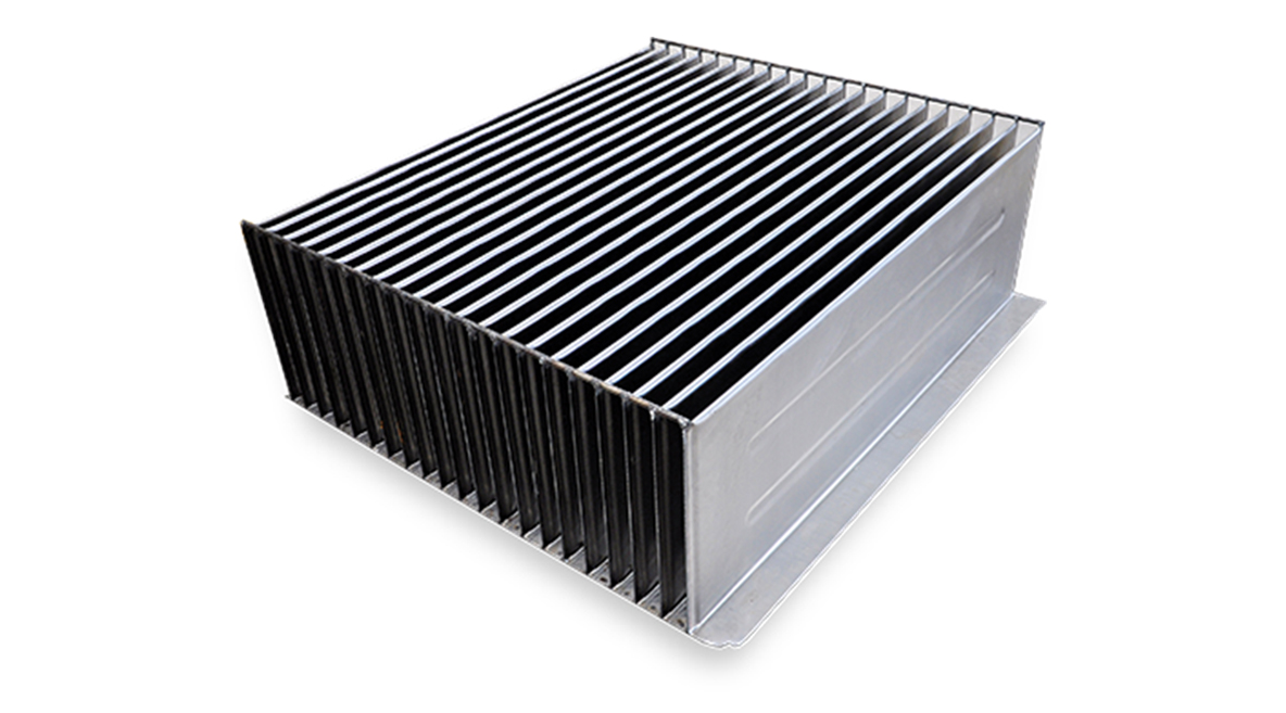
The rising temperature in the transformer core increases the kinetic energy of the cooling oil molecules. The cooling oil molecules with high kinetic energy are displaced by molecules with low kinetic energy and move towards the wall of the transformer tank. Fin walls provide cooling by increasing the contact surface of the heated oil with the atmosphere.

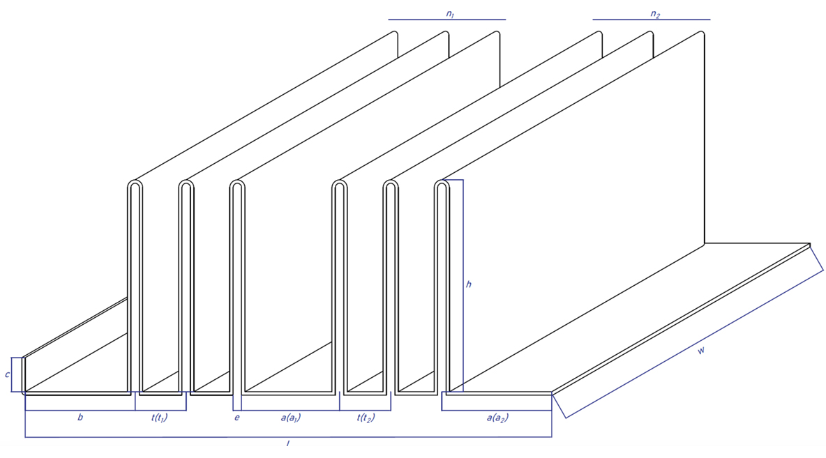
Fully automatic gas welding (MIG/MAG) welding machines are used to weld the fin walls used in transformer tanks. Fin walls can be manufactured with a maximum steel thickness of 1.2~1.5 mm, a width of 300~1600 mm, an internal cavity of 6-8 mm, a height of 50~400 mm and a distance between fins greater than 40 mm. Extra trans steel bars are welded on both sides of the welded panel to strengthen the fin wall.

Technical specifications for corrugated walls produced by fully automatic PLC wing forming machine are shown below:


Serial Number Description Code Unit Parameters
1 Sheet Width w mm 400~1,600
2 Sheet Thickness s mm 1.2~1.5
3 Fin Height h mm 50~400
4 Distance Between Fins t mm > 40
5 Inner Gap e mm 6-8
6 Number of Sets n pcs 1~4
7 Panel Length L mm < 2,600
8 Start-End Folding Length c mm 15~300
9 Start Distance b mm ≥ 40
10 Sheet Width a mm ≥ 40
CDM Transformer Machine
Ümit Mahallesi 2544.Sk No:3 Çankaya
Ankara / TÜRKİYE
+90 505 821 3660
All rights reserved. © 2022 by CDM Trafo San ve Tic.Ltd. Şti